English
 中文简体
中文简体 Español
 Português
 Deutsch
 русский

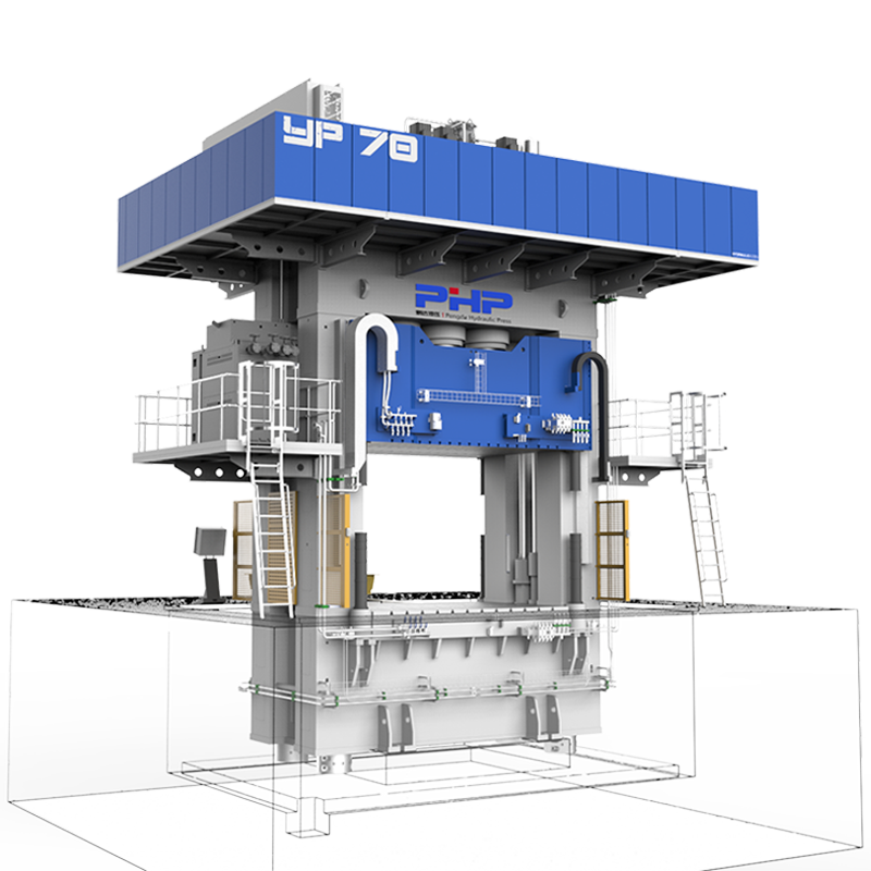
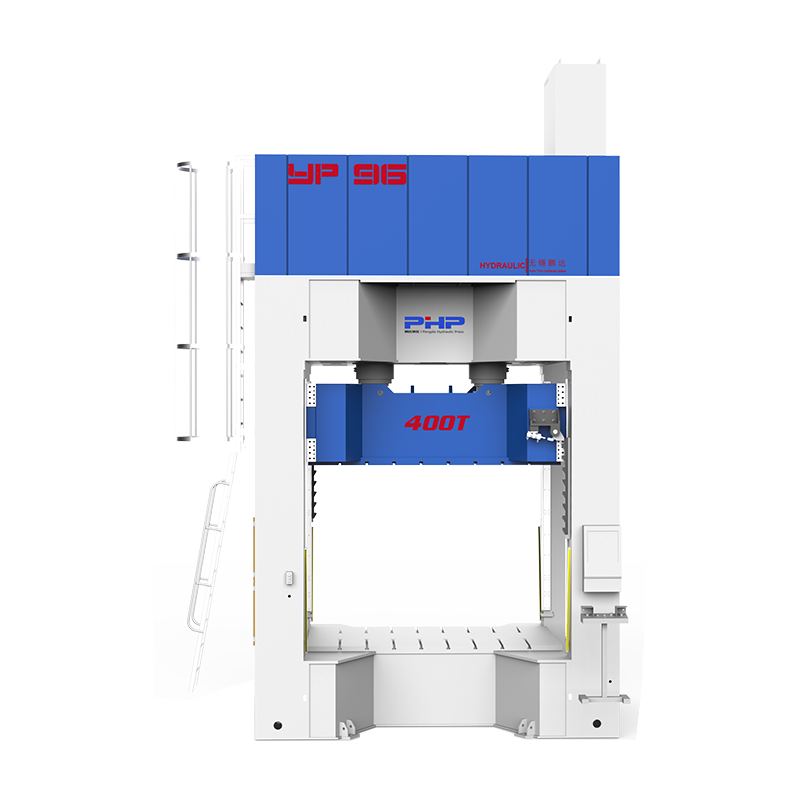
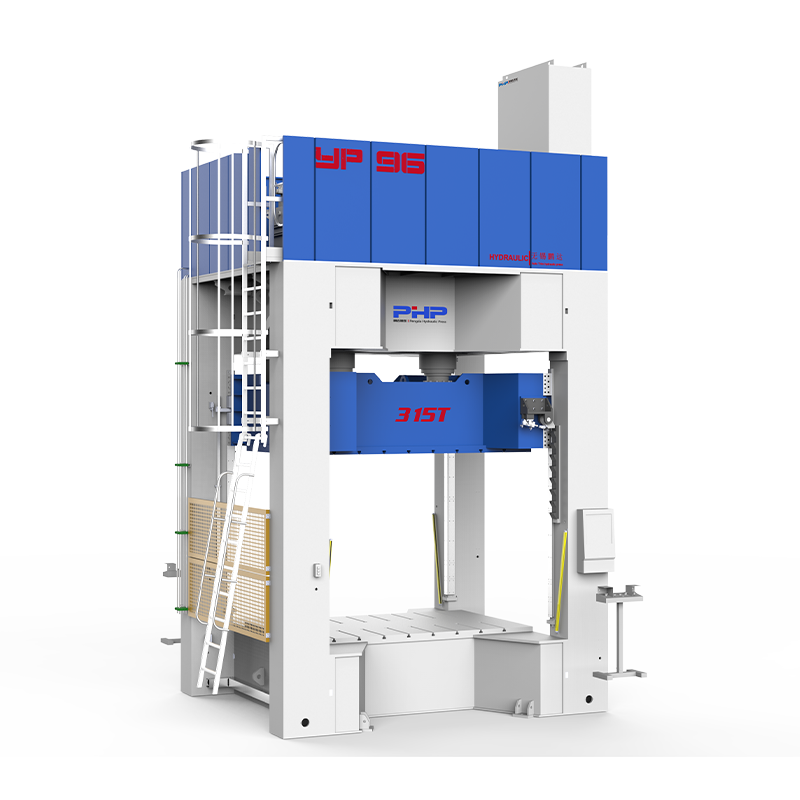
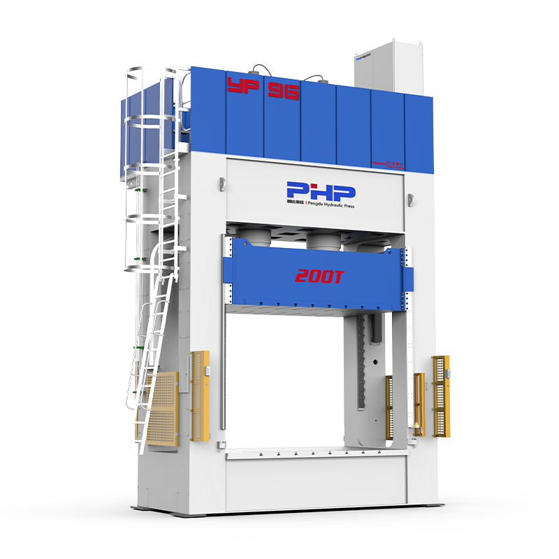


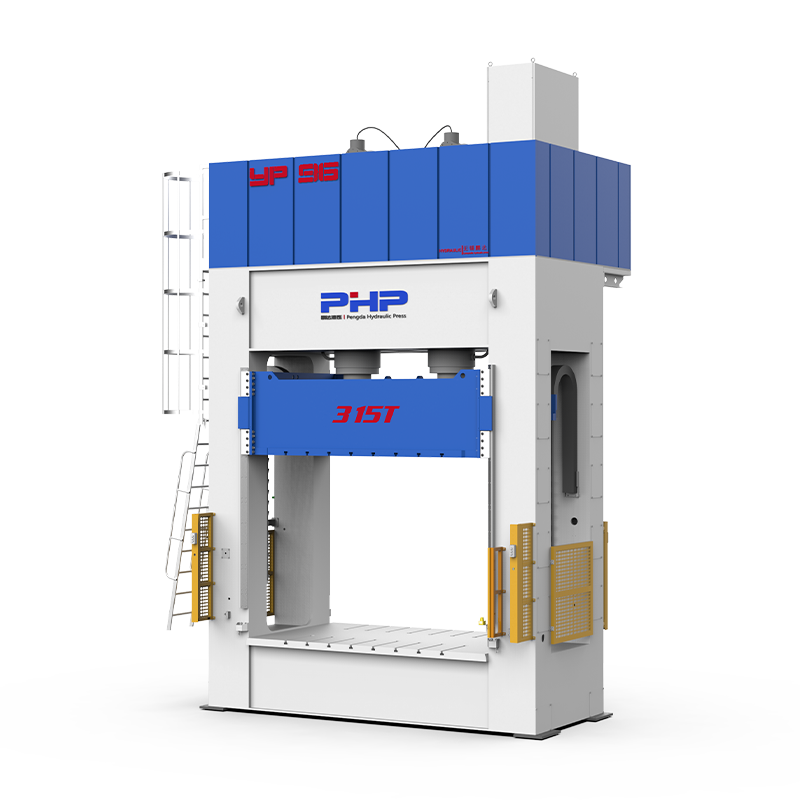
Sheet Molding Compound (SMC) compression molding is widely used for automotive components, electrical enclosures, battery covers, building products, access covers and other high-volume composite parts.
The process can deliver excellent repeatability, but only when the material, charge pattern, mold, temperature, press motion, pressure and cure cycle work together as a controlled system.
When defects appear, changing molding pressure alone is rarely the right answer. A blister may originate from trapped gas, moisture, poor venting or insufficient cure. A short shot may be caused by the SMC charge, mold temperature, closing profile or pressure development. Warpage may originate from fiber orientation, uneven heating, premature ejection or asymmetric material flow.
Identify → Measure → Isolate the Cause → Change One Variable → Validate → Standardize
Inhalt
- 1 1. Common SMC Molding Defects and How to Identify Them
- 2 2. Step-by-Step Troubleshooting Workflow for SMC Defects
- 3 3. Press Settings, Process Parameters and Cure Management
- 4 4. Tooling, Venting, Temperature Uniformity and Mold Maintenance
- 5 5. SMC Defect Troubleshooting Matrix
- 6 6. Inspection, SPC and Defect Prevention
- 7 7. Should an SMC Defect Be Repaired or Scrapped?
- 8 Prevent SMC Defects by Controlling the Entire Molding System
- 9 SMC Compression Molding Press Control Also Matters
- 10 SMC Compression Molding Press Solutions from Wuxi PengdaHZ
- 11 Frequently Asked Questions
- 11.1 What are the most common SMC molding defects?
- 11.2 What causes voids in SMC compression molding?
- 11.3 Why do SMC parts develop blisters?
- 11.4 What causes flow marks in SMC?
- 11.5 How can short shots be prevented?
- 11.6 How does molding pressure affect SMC defects?
- 11.7 How does mold temperature affect SMC part quality?
- 11.8 How can press settings reduce SMC molding defects?
1. Common SMC Molding Defects and How to Identify Them
SMC defects can generally be divided into surface defects, internal defects, filling defects and dimensional defects . Correct identification is the first step because defects that appear similar on the finished part may have completely different root causes.
Surface Defects
- Flow marks: directional or wavy surface patterns related to material flow.
- Fiber read-through: reinforcement becomes visible through the molded surface.
- Resin-rich areas: glossy or irregular areas containing excess local resin.
- Resin-starved areas: exposed fibers or rough surfaces due to insufficient resin coverage.
- Blisters: raised areas associated with trapped gas, moisture or incomplete cure.
- Pinholes: small surface cavities that may become more visible after painting or sanding.
Internal and Structural Defects
- Voids and internal porosity
- Delamination
- Internal cracking
- Incomplete fiber wet-out
- Localized resin starvation
- Foreign-material contamination
Dimensional Defects
- Warpage
- Twisting
- Uneven shrinkage
- Thickness variation
- Assembly misalignment
Filling Defects
- Short shot: the material fails to completely fill the cavity.
- Flash: excess material escapes through the mold parting line.
- Incomplete rib or boss filling
- Flow-front meeting defects
SMC-specific point: Fiber orientation should not be ignored during visual inspection. As the charge flows through the mold cavity, reinforcement can rotate and align with the flow direction. A visible surface pattern may therefore indicate a change in local material flow and potentially in local mechanical behavior.
| Defect | Typical Appearance | Quick Check | Advanced Inspection |
| Flow Marks | Directional or wavy surface lines | Visual inspection | Microscopy |
| Blisters | Raised bubbles or localized swelling | Visual or tap inspection | Ultrasonic inspection |
| Voids | Internal cavities | Section sample | Ultrasonic or CT |
| Delamination | Layer separation | Tap test or sectioning | Ultrasonic inspection |
| Warpage | Distorted geometry | Fixture or caliper | CMM or 3D scanning |
| Flash | Excess material along the parting line | Visual or caliper | Usually unnecessary |
| Short Shot | Incomplete cavity filling | Visual inspection | Usually unnecessary |
CT inspection can provide highly detailed information about internal defects, but it is normally more appropriate for complex, high-value or failure-analysis components than for routine high-volume production inspection.
2. Step-by-Step Troubleshooting Workflow for SMC Defects
Randomly adjusting several molding parameters at the same time makes troubleshooting slower. Even if the defect disappears, the engineer may not know which change actually solved the problem.
A more reliable approach is to establish a fixed troubleshooting sequence.
1
Confirm and Classify the Defect
Record the defect location, cavity number, production batch, material lot, mold temperature, cycle number, press program, operator and shift.
First determine whether the issue is cosmetic, dimensional, filling-related or structural .
2
Check Mold Temperature Distribution
Do not rely only on the value shown by the heating controller. Measure several actual mold locations, including the center, corners, thin sections, thick sections and recurring defect areas.
3
Check Charge Weight and Charge Pattern
Verify charge weight, sheet dimensions, number of layers, material orientation and charge position. Incorrect placement changes how far the SMC must flow before filling the cavity.
4
Check Material Condition
Review storage temperature, storage time, material maturation, contamination, moisture exposure and material-lot variation.
5
Review the Actual Press Curve
Do not review programmed setpoints alone. Examine the real position, velocity and pressure data recorded during the molding cycle.
Position → Velocity → Pressure Build-Up → Peak Pressure → Hold → Decompression → Opening
6
Inspect Venting and Tool Condition
Check vents, parting surfaces, mold wear, deposits, release-agent buildup, heating consistency and alignment.
7
Run Controlled Trials
Change one variable at a time whenever practical. Establish a baseline, modify one parameter, mold a defined number of samples and compare defect frequency before making another change.
3. Press Settings, Process Parameters and Cure Management
SMC compression molding is particularly sensitive to the interaction between temperature, flow time, press motion, molding pressure and cure . These factors should be treated as a process window rather than as isolated setpoints.
Mold Temperature
If mold temperature is too low, resin viscosity and cure behavior may prevent the process from reaching the desired cycle time or final mechanical properties.
If the temperature is too high, the SMC may begin curing before complete cavity filling. Possible consequences include:
- short shots;
- flow marks;
- poor surface finish;
- internal stress;
- incomplete flow into ribs and corners.
Conventional thermoset SMC is often processed using heated tooling around the 150°C range , but the correct window depends on resin chemistry, component thickness, geometry and the cure system.
Closing Speed
Closing too quickly may contribute to:
- trapped air;
- excessive material displacement;
- flash;
- unstable flow.
Closing too slowly may allow the resin to begin gelling before full cavity filling.
For this reason, an SMC press can use a multi-stage motion profile: fast approach followed by a controlled molding and flow stage.
Molding Pressure
Insufficient effective molding pressure may contribute to:
- incomplete filling;
- voids;
- poor compaction;
- dimensional inconsistency.
Excessive pressure may contribute to:
- excessive flash;
- fiber displacement;
- unnecessary mold loading;
- accelerated mold wear.
A reference SMC molding pressure may fall around 7-14 MPa in some applications, but this should never be treated as a universal setting.
Required pressure depends on material rheology, projected area, charge coverage, component geometry and flow distance.
Holding Time and Cure
Opening the mold before sufficient cure may cause post-mold deformation, blistering, poor mechanical properties or dimensional instability.
Holding considerably longer than required may improve neither quality nor performance, while directly increasing cycle time.
The objective is not simply to obtain the shortest cycle. It is to achieve the shortest repeatable cycle that consistently produces an acceptable part .
During advanced process development, DSC or other thermal-analysis methods can also be used to study cure behavior and validate the selected production window.
4. Tooling, Venting, Temperature Uniformity and Mold Maintenance
Many molding problems that initially appear to be material defects actually originate from the tool or from the interaction between the mold and press.
Venting
Air must escape from the cavity as SMC flows. Venting should therefore be evaluated around:
- final filling locations;
- distant corners;
- ribs;
- bosses;
- deep features;
- areas where multiple flow fronts meet.
Blocked or poorly positioned vents can contribute to short shots, surface defects, internal porosity, blisters and incomplete detail reproduction.
"Improve venting" is not a complete corrective action. The engineer should identify where the cavity actually fills last and where air or gas is becoming trapped.
Temperature Uniformity
A controller displaying 150°C does not prove that every region of the tool is actually at 150°C.
Uneven Mold Temperature → Uneven Cure → Uneven Shrinkage → Residual Stress → Warpage
Periodic mold temperature mapping should therefore include center areas, corners, major ribs, thick sections, thin sections and recurring defect locations.
Mold and Press Alignment
The investigation should also include:
- mold flatness;
- parting-line condition;
- guide components;
- platen parallelism;
- platen deflection;
- uneven loading.
If flash repeatedly appears on only one side of the molded part, simply changing pressure may hide the symptom without correcting a mold or platen alignment problem.
Preventive Mold Maintenance
- Clean vent channels regularly.
- Inspect the mold parting line.
- Remove excessive release-agent deposits.
- Verify heaters and temperature sensors.
- Inspect guide and alignment components.
- Repair damaged mold surfaces.
- Document recurring defect locations.
5. SMC Defect Troubleshooting Matrix
Because the same visible defect may have several causes, troubleshooting should compare material, press/process and mold factors together.
| Defect | Possible Material Cause | Press / Process Cause | Mold Cause | First Checks |
| Short Shot | Poor flow, aged material | Low effective pressure, unsuitable closing profile | Restricted flow, blocked vents | Charge pattern, press curve, venting |
| Flash | Excessive charge weight | Excessive pressure | Worn parting line or alignment problem | Charge weight and mold condition |
| Blister | Moisture or volatile components | Insufficient cure | Poor gas evacuation | Material storage, cure cycle, vents |
| Warpage | Uneven fiber orientation | Premature ejection | Uneven mold temperature | Temperature map and material flow |
| Voids | Poor wet-out or trapped air | Insufficient compaction | Poor venting | Charge stacking, pressure curve, vents |
| Flow Marks | Material flow behavior | Unsuitable closing speed | Flow restriction | Charge placement and velocity profile |
| Fiber Exposure | Resin distribution variation | Excessive material movement | Local flow geometry | Material condition and charge pattern |
| Dimensional Variation | Batch variation | Position or pressure inconsistency | Thermal variation | Press repeatability and mold temperature |
6. Inspection, SPC and Defect Prevention
A stable SMC process should monitor the variables that create the part instead of relying only on finished-part inspection.
| Parameter | Monitoring Method |
| Charge Weight | Digital scale |
| Material Lot | Production traceability record |
| Mold Temperature | Thermocouples plus periodic temperature verification |
| Closing Position | Press position sensor |
| Closing Velocity | Press controller / cycle data |
| Peak Pressure | Pressure transducer / press data |
| Holding Pressure | Recorded cycle curve |
| Cure Time | PLC cycle record |
| Part Weight | Digital scale |
| Thickness | Caliper or CMM |
| Critical Dimensions | Gauge or CMM |
| Warpage | Inspection fixture or CMM |
| Internal Voids | Sampling section or ultrasonic inspection |
Use SPC Where It Matters
Control charts can be applied to variables such as:
- charge weight;
- mold temperature;
- cycle time;
- critical dimensions;
- part weight;
- peak pressure;
- holding pressure.
Cpk requirements should be based on the customer's drawing, control plan, PPAP requirements or internal quality standard rather than applying one universal capability target to every SMC component.
A major advantage of SPC is that it can identify process drift before a large quantity of defective components is produced.
7. Should an SMC Defect Be Repaired or Scrapped?
Not every molded defect is suitable for repair. The correct disposition depends on part criticality, defect depth, location, customer requirements, mechanical loading and electrical or environmental requirements.
| Defect | Typical Disposition |
| Minor Cosmetic Pinhole | Cosmetic repair may be possible |
| Minor Surface Imperfection | Sanding or coating may be permitted |
| Small Non-Critical Edge Damage | Controlled repair may be possible |
| Internal Delamination | Engineering evaluation required |
| Significant Structural Void | Frequently reject |
| Major Short Shot | Normally reject and remold |
| Severe Warpage | Reject unless approved dimensional rework exists |
| Structural Crack | Engineering review or reject |
For structural automotive components, electrical insulation parts and other safety-relevant products, repairs should not be introduced without documented engineering approval and validation.
Prevent SMC Defects by Controlling the Entire Molding System
Recurring SMC defects should not automatically be blamed on the resin, mold or press. A reliable process requires coordinated control of all important variables.
Material Charge Pattern Mold Temperature Press Motion Pressure Cure
The most useful troubleshooting question is therefore not: "Which setting should we increase?"
A better question is: "Which measurable process condition changed before the defect appeared?"
By collecting material information, mold-temperature data, actual press curves, part measurements and defect locations, manufacturers can move away from trial-and-error troubleshooting and toward repeatable process control.
SMC Compression Molding Press Control Also Matters
For high-volume SMC molding, the hydraulic press should provide sufficient control and repeatability throughout the entire compression cycle.
Important press-related factors include:
- closing velocity control;
- multi-stage closing profiles;
- pressure build-up control;
- holding-pressure stability;
- ram position repeatability;
- platen parallelism;
- controlled decompression;
- cycle-data recording.
Actual press curves can also help production engineers distinguish equipment-related variation from problems caused by SMC material, tooling or cure conditions.
SMC Compression Molding Press Solutions from Wuxi PengdaHZ
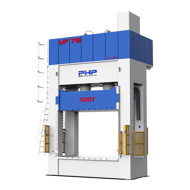
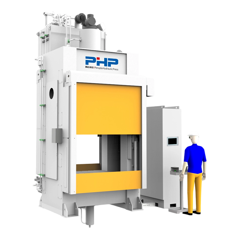
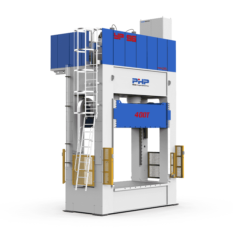
Wuxi PengdaHZ Intelligent Equipment Co., Ltd. develops hydraulic press solutions for SMC and composite compression molding applications.
When planning a new SMC production line or upgrading an existing molding process, press selection should be based on the actual component and process requirements rather than tonnage alone.
Useful information for equipment evaluation includes SMC material type, finished-part dimensions, projected molding area, required pressure, mold dimensions and weight, stroke, daylight, target cycle time, production capacity and automation requirements.
Visit wuxipd.com for more information about SMC hydraulic presses and composite compression molding equipment.
Frequently Asked Questions
What are the most common SMC molding defects?
Common defects include flow marks, fiber read-through, resin-rich or resin-starved areas, blisters, pinholes, porosity, internal voids, delamination, cracks, warpage, flash and short shots.
What causes voids in SMC compression molding?
Voids may result from trapped air between charge layers, poor material wet-out, gases generated during molding, poor venting, unsuitable charge placement or insufficient effective compaction.
Why do SMC parts develop blisters?
Possible causes include moisture, volatile components, trapped gas, incomplete cure, local temperature differences or opening the mold before sufficient cure has developed.
What causes flow marks in SMC?
Flow marks may be influenced by charge placement, fiber orientation, local resin distribution, mold geometry, temperature and the press closing-speed profile.
How can short shots be prevented?
Check charge weight and placement first, followed by material condition, mold temperature, venting, actual press velocity and position curves and effective molding pressure.
How does molding pressure affect SMC defects?
Insufficient pressure can contribute to poor filling, voids and dimensional inconsistency. Excessive pressure can increase flash, fiber movement, tool loading and mold wear.
How does mold temperature affect SMC part quality?
Mold temperature affects material viscosity, flow time, curing rate, shrinkage, surface quality, cycle time and dimensional stability. Temperature uniformity across the entire tool is also critical.
How can press settings reduce SMC molding defects?
A properly configured SMC press provides repeatable control over approach speed, molding velocity, pressure build-up, holding pressure, ram position, cure time and mold opening. Recording the actual cycle curve also makes troubleshooting more systematic.